Fundamentals of Fluids and Fluid Systems

Viscosity
In order to understand fluid systems it is critical to understand the basic properties of fluids.  This article provides the reader with a fundamental understanding of viscosity, viscosity index, compressibility, and the advantages of petroleum based hydraulic fluids.

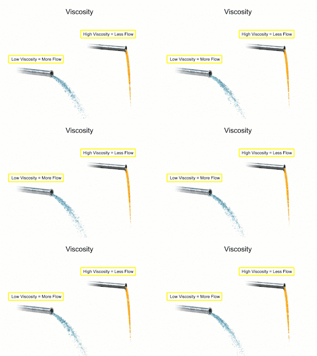
Fluids used in mechanical systems come in many different types. The type of fluid chosen for a particular application depends on its characteristics. One of the most important characteristics of a fluid is its viscosity. Viscosity is defined as a fluids resistance to flow. Fluids with low viscosity flow very easily. Water is a type of fluid with low viscosity. Fluids with high viscosity are more resistant to flow. Honey is a type of fluid with a high viscosity, therefore honey is more viscous than water.


Viscosity index
The viscosity index refers to
changes in viscosity relating
to changes in temperature.
Another characteristic of fluids is the viscosity index. This rating relates the flow of a fluid with its temperature. Many fluids begin to flow more easily as temperature increases. The viscosity index is the measurement of this characteristic. A high viscosity index indicates a small viscosity change with temperature. A low viscosity index indicates a large viscosity change with temperature.

Compressibility is another characteristic of fluids. It measures the change in volume of a fluid as a response to a change in pressure. Fluids such as gases are highly compressible. Their volumes change significantly when placed under pressure. Liquid fluids also have a compressibility factor. Water and petroleum based hydraulic fluid are almost completely incompressible. They don't compress when put under pressure. This characteristic is what allows them to be used to transmit power in fluid systems.
Gas compressibility
Gases are highly
compressible.

Years ago, water was used as the first hydraulic fluid because there was no other liquid available in such large quantities at such a low cost. There are some major draw backs to using water as a working fluid. Due to its low viscosity, it is difficult to pump. Additionally, the speed at which it flows through the system causes an effect known as wire drawing. Wire drawing occurs when the water flow erodes, or scores, a pathway in the metal of machinery as it goes around corners and through orifices. It also has corrosive effects on metal machinery.

Over time petroleum based hydraulic fluids have become much more cost-effective. For starters, it has a lower specific gravity than any other liquid and can be pumped with less power loss. It also lubricates as it works through the system and has little corrosive effects on metal machinery. Flammability is an issue, but with the development of synthetic oils, alternatives to water remain the preferred working fluid.
Liquid compressibility
Water and hydraulic
fluid are almost
completely incompressible.

Several factors should be considered when designing a fluid system that uses a petroleum-based hydraulic fluid. The first is cleanliness. Oil never wears out but it can become so contaminated that it is unfit for further use. Fluid systems frequently employ filters throughout the system to help reduce contaminants. They may also require complete fluid replacement after certain time intervals and this can become cost prohibitive with larger systems. Another factor common to hydraulic fluids are the use of additives. Additives can be used to reduce aeration and the production of bubbles as the fluid travels rapidly throughout the system. They can be used to administer corrosion inhibitors within the reservoir and they can be used as a multi-agent which helps the fluid resist mixing with water.

The choice of modern fluids is so wide that when designing a new system fluid characteristics such as viscosity, viscosity index, cleanliness, filtration and additives should be considered as early as possible in the design process.

Always consult with a fluid systems expert before selecting materials and equipment in any hydraulic system. Their experience and knowledge will help you design an efficient, safe, and cost-effective solution.

For more information, visit https://fluidsystems.processcontrolsolutions.com or call (800) 462-5769.


Information courtesy of www.eicc.edu and funded through a Department of Labor grant under creativecommons.org/licenses/by/4.0/.
Transmitters Used in Industrial Process Control

Pressure transmitter
Pressure transmitter (ifm)
Transmitter is a term used to describe a family of process control field devices. They receive input from a connected process sensor, then convert the sensor signal to an output signal using a transmission protocol. The output signal is passed to a monitoring, control, or decision device for use in documenting, regulating, or monitoring a process or operation.

In general, transmitters accomplish three steps, including converting the initial signal twice. The first step is the initial conversion which alters the input signal to make it linear. After an amplification of the converted signal, the second conversion changes the signal into either a standard electrical or pneumatic output signal that can be utilized by receiving instruments and devices. The third and final step is the actual output of the electrical or pneumatic signal to utilization equipment - controllers, PLC, recorder, etc.

Transmitters are available for almost every measured parameter in process control, and are often referred to according to the process condition which they measure.
Level transmitter
Level transmitters (ifm)


Some examples.

  • Pressure transmitters
  • Temperature transmitters
  • Flow transmitters
  • Level transmitters
  • Vibration transmitters
  • Current, voltage & power transmitters
  • PH, conductivity, dissolved gas transmitters, etc.
Output signals from transmitters, when electrical, often are either voltage (1-5 or 2-10 volts DC) or current (4-20 mA). Power requirements can vary among products, but are often 110/220 VAC or 24 VDC.  Low power consumption by electrical transmitters can permit some units to be "loop powered", operating from the voltage applied to the output current loop. These devices are also called "two-wire transmitters" because only two conductors are connected to the unit. Unlike the two wire system which only needs two wires to power the transmitter and carry the analog signal output, the four-wire system requires four separate conductors, with one pair serving as the power supply to the unit and a separate pair providing the output signal path. Pneumatic transmitters, while still in use, are continuously being supplanted by electrical units that provide adequate levels of safety and functionality in environments previously only served by pneumatic units.
Pressure transmitter
(Winters)

Many transmitters are provided with higher order functions in addition to merely converting an input signal to an output signal. On board displays, keypads, Bluetooth connectivity, and a host of industry standard communication protocols can also be had as an integral part of many process transmitters. Other functions that provide alarm or safety action are more frequently part of the transmitter package, as well.

Wireless transmitters are also available, with some operating from battery power and negating the need for any wired connection at all. Process transmitters have evolved from simple signal conversion devices to higher functioning, efficient, easy to apply and maintain instruments utilized for providing input to process control systems.

To lean more about transmitters, visit https://flowcontrol.processcontrolsolutions.com/ or call Process Control Solutions at 800-528-8997.

EIM TEC2 Electric Actuator with Model 500 Quick-Start Guide

EIM TEC2 Electric Actuator
This Emerson/EIM electric valve actuator is the next generation of the non-intrusive TEC2000 actuator. Robust and compact design that are widely used on valves for marine, oil and gas, chemical, power, and water and wastewater applications.

Features:
  • Superior corrosion protection polyester powder-coating, inside and out, for all environments, 316 stainless steel cover screws, marine-grade, low copper content, aluminum provides compartment and covers with extra corrosion protection.
  • Separately Sealed Terminal Chamber (STC), dual sealed, allows installation wiring to be performed without exposing electronic control components.
  • Anti-condensation space heater thermostat prevents internal condensation due to temperature cycling with solid-state thermo-statically controlled to turn heater off.
  • Large LCD message screen uses icons and text to display status of valve and provide diagnostic data, easy to guide operator through multi-language capable, calibration, setup, and diagnostics.
  • Non-penetrating control knobs operate with vibration resistant Hall-effect switches enabling actuator calibration and diagnostics without opening covers.
  • Double-reduction motor gears provide flexibility, enables worm gearing to operate at lower speeds for minimum wear and long life.
  • Self-locking gearing even during declutching and manual override and valve stem cannot be back-driven under high process pressures or heavy weight of gate.
TEC2 Electric Actuator with Model 500 Quick-Start Guide:

Happy 4th of July from Process Control Solutions!


"America was built on courage, on imagination and an unbeatable determination." 

Harry S. Truman

Process Control Solutions: Delivering Innovation, Professionalism, Knowledge and Experience


Control Systems - Turn-key process automation and systems integration services, including SCADA, PLC & HMI programming, industrial control panels fabrication, product testing, and Wonderware integration.

Fluid Systems - Specializes in the design and manufacture of custom fluid power systems, test stands, and special machinery.

Fluid Power - Your source for fluid power equipment and control products.

Flow Control - Your source for valves, valve actuation, pressure relief devices and other related accessories as well as services required by the diverse process industry.

Field Services & Repair - Industrial service company with decades of experience in flow solutions, on-site and off-site repair, maintenance and installation, and product sales and application support.

Understanding Sequence Diagrams in Fluid Power

A sequence diagram is a type of illustration that graphically represents the physical state of each component in a system sequencing charts can be used in electrical fluid or combined systems. They are used to aid the user in understanding the operation of the system and to help identify which components are actuated or energized at any given time during the system cycle. Many sequence diagrams are used as auxiliary documentation to assist with illustrating the information conveyed on schematics or circuit diagrams. While there is no official standard for drawing a sequence diagram, most are drawn with the time lapse on the horizontal axis and the action accomplished on the vertical axis. to build a sequence diagram each major component is assigned a horizontal line. the width of the line shows the time period during the cycle that each component is actuated or energized.

This video provides a visual understanding of the sequence diagram, and its associated electrical and mechanical schematic diagrams.

Process Controls Solutions
https://processcontrolsolutions.com
(800) 462-5769

What Are Custom Hydraulic Power Units?

HPU for assembling automotive drivelines
Custom HPU's for assembling automotive drivelines
(Process Control Solutions)
There are many manufacturers of standard model hydraulic power units (HPUs), all of which provide an off-the-shelf, readily available, generically configured system. These standard HPUs are a quick and easy solution when hydraulic power is needed. Many times though, standard HPU's don't fit the bill, and a more customized unit is needed. What to do then?

Custom Designed HPUs
Custom manufactured HPUs are hydraulic power solutions designed to fit a customers exact requirement. Customization generally involves the inclusion of special manifolds, cooling fans, level controls, heat exchangers, filtration systems, relief valves, pressure switches and temperature control.

Why Custom?
Certain processes require unique features. A user's proprietary application might require higher pressures, faster response, or continuous operation. While is sounds antithetical, custom HPUs can actually be less expensive than prebuilt, standard model units. This is because custom units are sized and equipped with only the components the application requires. So in actuality, deciding on a custom HPU can potentially lower initial cost and increase profits by improved long-term performance.

Applications
Custom hydraulic power units are used in widely in compacting applications, automotive manufacturing equipment, transportation equipment, mining equipment, agricultural equipment, and in many industrial applications.

Vendor Selection
The variety of specialized features for hydraulic power units is endless, making engineering depth and broad application experience very important. Make sure this is proven when interviewing a prospective vendor. The more diversified they are in applying hydraulic power units, the more likely you'll have a positive outcome.