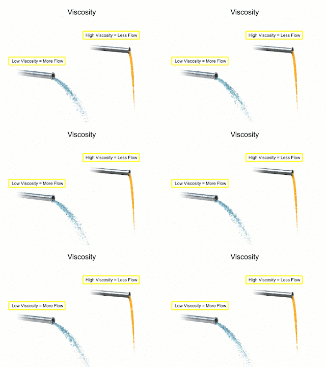
Fluids used in mechanical systems come in many different types. The type of fluid chosen for a particular application depends on its characteristics. One of the most important characteristics of a fluid is its viscosity. Viscosity is defined as a fluids resistance to flow. Fluids with low viscosity flow very easily. Water is a type of fluid with low viscosity. Fluids with high viscosity are more resistant to flow. Honey is a type of fluid with a high viscosity, therefore honey is more viscous than water.
 |
| The viscosity index refers to changes in viscosity relating to changes in temperature. |
Compressibility is another characteristic of fluids. It measures the change in volume of a fluid as a response to a change in pressure. Fluids such as gases are highly compressible. Their volumes change significantly when placed under pressure. Liquid fluids also have a compressibility factor. Water and petroleum based hydraulic fluid are almost completely incompressible. They don't compress when put under pressure. This characteristic is what allows them to be used to transmit power in fluid systems.
 |
| Gases are highly compressible. |
Years ago, water was used as the first hydraulic fluid because there was no other liquid available in such large quantities at such a low cost. There are some major draw backs to using water as a working fluid. Due to its low viscosity, it is difficult to pump. Additionally, the speed at which it flows through the system causes an effect known as wire drawing. Wire drawing occurs when the water flow erodes, or scores, a pathway in the metal of machinery as it goes around corners and through orifices. It also has corrosive effects on metal machinery.
Over time petroleum based hydraulic fluids have become much more cost-effective. For starters, it has a lower specific gravity than any other liquid and can be pumped with less power loss. It also lubricates as it works through the system and has little corrosive effects on metal machinery. Flammability is an issue, but with the development of synthetic oils, alternatives to water remain the preferred working fluid.
 |
| Water and hydraulic fluid are almost completely incompressible. |
Several factors should be considered when designing a fluid system that uses a petroleum-based hydraulic fluid. The first is cleanliness. Oil never wears out but it can become so contaminated that it is unfit for further use. Fluid systems frequently employ filters throughout the system to help reduce contaminants. They may also require complete fluid replacement after certain time intervals and this can become cost prohibitive with larger systems. Another factor common to hydraulic fluids are the use of additives. Additives can be used to reduce aeration and the production of bubbles as the fluid travels rapidly throughout the system. They can be used to administer corrosion inhibitors within the reservoir and they can be used as a multi-agent which helps the fluid resist mixing with water.
The choice of modern fluids is so wide that when designing a new system fluid characteristics such as viscosity, viscosity index, cleanliness, filtration and additives should be considered as early as possible in the design process.
Always consult with a fluid systems expert before selecting materials and equipment in any hydraulic system. Their experience and knowledge will help you design an efficient, safe, and cost-effective solution.
For more information, visit https://fluidsystems.processcontrolsolutions.com or call (800) 462-5769.
Information courtesy of www.eicc.edu and funded through a Department of Labor grant under creativecommons.org/licenses/by/4.0/.


