Showing posts with label Missouri. Show all posts

Single Source Providers for Valve Automation Solutions: Your Best Bet

It’s just easier and much more efficient to do business with a single valve and valve automation supplier. This is why Process Control Solutions' Flow Control Group provides complete turnkey valve, automation and control systems.

valve and valve automation
PCS custom valve automation systems are precisely engineered based on an end-user’s specific application. The PCS process includes application review and recommendation of valve, actuator, control accessories (filter regulator, solenoid valve, positioner ) and all mounting devices.

Every Process Control Solutions valve automation system comes with support documentation including installation manuals, quick service guides, drawings, warranty certificate and maintenance schedules. Everything the end-user needs for maintenance and operation of the valve, actuator, controls, and optional components. The benefits are obvious:

Benefits:
  • Reduces costs
  • Optimizes customer service efficiency
  • Deal with a single entity with proven expertise.
  • Simplified ordering, procurement, and deployment.
  • Centralized documentation and support.
For more information about valve automation systems, contact Process Control Solutions by visiting https://flowcontrol.processcontrolsolutions.com or by calling (800) 462-5769.

Industrial Valve and Actuator Symbols

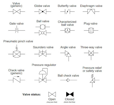
This post shows industrial valve and actuator symbols found in different types of technical
diagrams used to document instrument systems. Valve symbols typically describe the position, number of ports, and flow control method of particular valves. Actuator symbols generally describe the motive force and control options.

Valve Symbols (generic valve, globe valve, butterfly valve, diaphragm valve, gate valve, ball valve, characterized ball valve, plug valve, pneumatic pinch valve, angle valve, 3-way valve, generic check valve, pressure regulator, ball check valve, safety relief valve.) 

Industrial Valves
Click for larger view.


Actuator Symbols (diaphragm, electric motor, solenoid, piston, diaphragm w/ hand jack, electric motor w/ hand jack, hand (manual), electro-hydraulic, diaphragm w/ positioner, piston w/ positioner.)

Industrial Actuators
Click for larger view.

For application information on industrial valves and actuators, contact Process Control Solutions by calling (800) 462-5769 or visit their website at https://processcontrolsolutions.com.


Durkin Equipment Company and ABB Process Instrumentation


Durkin Equipment Co., is a premier provider of systems integration services and process instrumentation in the St. Louis, MO area, and is the industrial and municipal partner for ABB process instrumentation including pressure, temperature, level, and flow controls, process analyzers and actuators and positioners. A listing of the ABB products Durkin Equipment expertly applies and supports are:

Process Instrumentation
  • Magnetic Flow Meters
  • Differential Flow Meters
  • Vortex & Swirl Meters
  • Coriolis Flow Meters
  • Ultrasonic Flow Meters
  • Rotameters
  • Pressure Transmitters
  • Temperature Transmitters
  • Level Measurement
  • Positioners & Actuators
  • Recorders
  • Controllers
Process Analyzers
  • PH  analyzer
  • ORP Analyzer
  • Conductivity Analyzer
  • Water analyzers
  • Combustion Analyzers
  • Liquid analyzers
  • Toxic Gas Detectors

Process Control Solutions in 45 Seconds

Process Controls Solutions is a value-added distributor and application specialist of process equipment and control products. Additionally, we provide systems integration services and specialize in the design, build, and startup of process and industrial control systems. With decades of experience supporting fluid power, flow control, instrumentation and control system needs, we have accumulated the knowledge to provide innovative solutions for virtually any process application requirement.

https://processcontrolsolutions.com
(800) 462-5769

The D4 Hygienic Double Seat Mix Proof Valve from SPX Flow

D4 Hygienic Double Seat Mix Proof Valve
The SPX D4 Hygienic Double Seat Mix Proof Valve
SPX FLOW is pleased to introduce the hygienic D4 double seat, mix proof valve series. The D (for double seat) valve is used for the reliable separation of dissimilar fluids such as process and CIP solutions. These next-generation valves help fulfill today's customer demands for process flexibility, increased productivity, rapid return on investment, and improved product quality.

The D4 series provides multiple options including non-seat lift, seat lift and ultra hygienic.  This series has high value with low life cycle costs which include:
Reduced inventory costs
  • Low chemical and water loss consumption
  • Low air consumption and air supply requirements
  • Long housing ports to ease manifold building
The lightweight D4 series also makes routine maintenance and handling easy.  These valves are suited for a variety of applications such as milk, soft drinks, dressings, soups, brewing, wine, cleaners and extracts.

Watch the movie below for more detail one the D4. To discuss a specific application, please contact:

Process Control Solutions
https://processcontrolsolutions.com
(800) 462-5769

Wika Pressure and Temperature Measurement Product Catalog

WIKA is the leading global manufacturer of pressure and temperature measurement instrumentation, producing more than 43 million pressure gauges, diaphragm seals, pressure transmitters, thermometers and other instruments annually. WIKA’s extensive product line, including mechanical and electronic instruments, provides measurement solutions for any application in a large variety of industries.

Products include:
  • Mechanical Pressure
  • Electronic Pressure
  • Diaphragm Seals
  • MechanicalTemperature
  • Electronic Temperature 
  • Accessories
Contact Process Control Solutions for all your WIKA requirements.

Process Control Solutions
https://processcontrolsolutions.com
(800) 462-5769

Pinch Valves Provide Superior Performance and Low Total Cost of Ownership for Lime Slurry

Calcite Limestone
Calcite Limestone
Lime is a basic industrial chemical that has widespread use in many chemical processes. It is also used extensively in food and beverages production processes. Examples of chemical industry applications are the manufacture of caustic soda (sodium hydroxide), the production of acetylene, the production of the fertilizer calcium cyanamide, the purification of citric acid, the production of pool chlorine, and the making of road de-icing chemicals. Examples of lime use in the food and beverage industry are the production of sugar, the processing of milk and cream, the production of baking powder, the ripening and storage of fresh fruits and vegetables, and the production of corn tortilla's.

Lime is normally stored as a dry powder and mixed with water or additional chemicals to create a lime slurry that can be pumped through pipes and added to the production stream as needed. The management of lime slurry to process piping, valves, and instrumentation is challenging because of lime's physical and chemical properties. Lime slurry is slightly abrasive and can be quite corrosive depending upon the other chemicals involved. Lime also has a tendency to build up as scale inside pipes and valves. This scaling can severely inhibit the operation of traditional quarter-turn valves and restrict flow. Another concern is the problem of dewatering, which happens at the point where pressure is shut off. The upstream pressure in the line ahead of a flow control valve will force liquid out of the lime, leaving a very hard, dry plug behind. The plug is hard enough to prevent the opening of a ball, plug, or butterfly valve. A significant maintenance headache occurs when this happens.

Pinch valve in lime slurry service
Pinch valves in lime slurry service.
Because of their simple, elastomer wetted, cavity-free design, rubber sleeved pinch valves have proven over time to be the best long-term solution for slurries. Pinch valves provide an excellent seal with tight shut-off, and because of their robust & straight-through design, are able to open and close regardless of obstacles in the flow tube. Other benefits making pinch valves ideal for lime slurry use are low maintenance (no bearings, seals or packing), fast opening and closing, self-cleaning and high Cv.

Control Valve
Control Valve
(Red Valve)

Pinch valves are available in 1" through 96" diameters, can be operated manually or via pneumatic or electric actuators, and perform excellently as control valves.

For any abrasive and corrosive service, and particularly for lime slurry service, pinch valves provide an inexpensive flow control solution with superior performance and very low total cost of ownership.

For more information on the proper application of pinch valves contact Process Control Solutions by calling (800) 462-5769 of by visiting https://flowcontrol.processcontrolsolutions.com.

What is a Triple Offset Butterfly Valve?

Triple Offset Butterfly Valve
Designed as an alternative to the traditional gate valves with metal-to metal seats, triple offset butterfly valves provide distinct advantages over traditional gate valves, namely lower weight, zero-leakage, ease in automation, and capable of being used for modulating service.

Triple offset butterfly valves are designed to fill the demand for an alternate solution to gate valves and ball valves. They are preferred when weight, space, performance, and the ability to modulate to the process flow are an issue. Typically available in sizes 3" through 48", and in 150, 300 and 600 pressure classes, they're rated for operation from -50 deg. F. through 750 deg. F.

Face-to-Face dimensions are standard per AMSE B16.10, API 609, ISO 5752 and BS 5155. with API 598. Triple Offset Butterfly valves allow for bidirectional flow capability while complying with API 598 for seat leak testing, and are inherently fire safe by design. Finally, these valves offer anti-blowout stems and field replaceable seats for both disc seat and the body seat.

Triple Eccentric Disc-Shaft Design (see diagram below)


1st Offset: It is accomplished by moving the centerline of the shaft away from the seating plane.
2nd Offset: It is accomplished by moving the centerline of the shaft offset from the centerline bore of the valve.

These two design features cause the disc to open and close relative to the body seat in a “camming” action and effectuate the position seated valve design which is typical of the High Performance Butterfly Valve, however there is still contact between the disc and the seat in the first several degrees of opening and closing which can cause premature wear of the seat in the general areas.

In order to achieve an API 598 Shut Off classification a 3rd offset needed to be introduced to make the valve a “torque seated” design with graphite and metal seating surfaces.

3rd Offset: It is accomplished by adjusting the cone angle created by the 1st and 2nd offset angles at some point downstream of the valve in the center of the piping to the adjacent piping wall as depicted in the illustration below “Sticking tendency”. By incorporating the 3 offsets into one design typical of gate valves is eliminated with seat contact throughout the entire stroke reducing run torques and improving actuator modulating performance at the same time.

Triple Eccentric Disc-Shaft
Diagram: Triple Eccentric Disc-Shaft Design
(click for larger view).

Applicable Industries
  • Refinery
  • Chemical
  • Petrochemical
  • Power
  • Steam Generation
  • Water/Waste Water Treatment
For more information, contact Process Control Solutions by visiting https://flowcontrol.processcontrolsolutions.com or by calling (800) 462-5769.

Advantages of Rotary Pneumatic Actuators Over Rack & Pinion and Scotch Yoke Actuators

Rotary Pneumatic Actuator
Rotary actuator control valve.
(Easytork)
By virtue of their design, pure rotary-to-rotary actuators experience zero repeatability loss, regardless of how long the actuator is used, making them a better choice than linear-to-rotary actuators.

The Problem

Rack and pinion or scotch-yoke actuators on the market today convert linear to rotary movement. The wear between the racks and pinion will worsen over time, increasing the repeatability losses. Rack and pinion, and diaphragm actuators, all require gears to convert linear motion to rotary motion, adding rack and gearing tolerances which add backlash or hysteresis. Over time, wear in the rack and gearing areas add additional backlash or hysteresis, degrading the actuators repeatability.

The Solution

Pneumatic vane actuators are pure rotary-to-rotary, meaning all motion produced by the vane actuator transfers unfiltered to the valve stem with zero motion loss. Unlike linear-to-rotary actuators, where the pinion experiences wear and lost motion which leads to increased backlash over time, rotary-to-rotary designs do not have to contend with the increased backlash.

For more information, contact:
Process Control Solutions
https://flowcontrol.processcontrolsolutions.com
(800) 462-5769

Fundamentals of Fluids and Fluid Systems

Viscosity
In order to understand fluid systems it is critical to understand the basic properties of fluids.  This article provides the reader with a fundamental understanding of viscosity, viscosity index, compressibility, and the advantages of petroleum based hydraulic fluids.

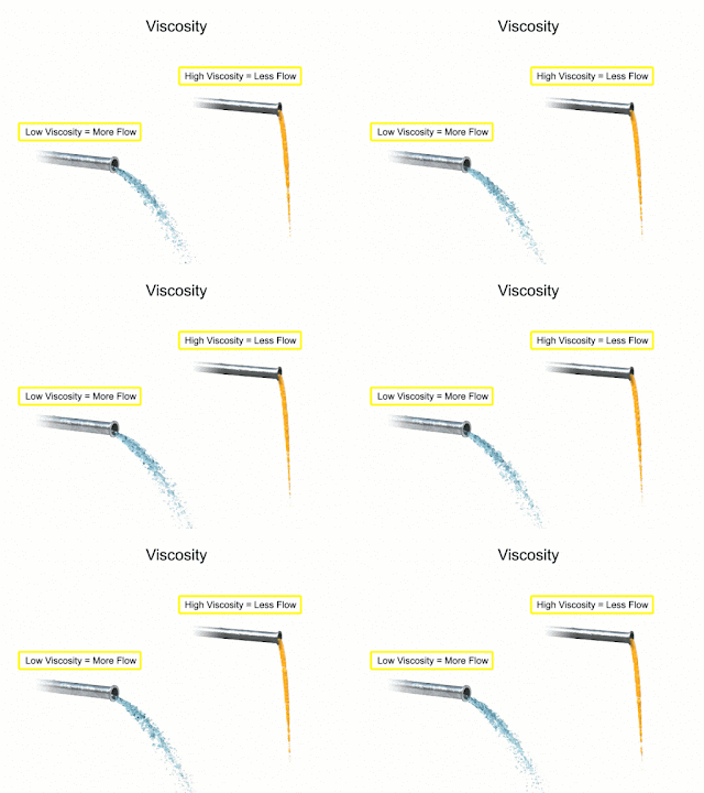
Fluids used in mechanical systems come in many different types. The type of fluid chosen for a particular application depends on its characteristics. One of the most important characteristics of a fluid is its viscosity. Viscosity is defined as a fluids resistance to flow. Fluids with low viscosity flow very easily. Water is a type of fluid with low viscosity. Fluids with high viscosity are more resistant to flow. Honey is a type of fluid with a high viscosity, therefore honey is more viscous than water.


Viscosity index
The viscosity index refers to
changes in viscosity relating
to changes in temperature.
Another characteristic of fluids is the viscosity index. This rating relates the flow of a fluid with its temperature. Many fluids begin to flow more easily as temperature increases. The viscosity index is the measurement of this characteristic. A high viscosity index indicates a small viscosity change with temperature. A low viscosity index indicates a large viscosity change with temperature.

Compressibility is another characteristic of fluids. It measures the change in volume of a fluid as a response to a change in pressure. Fluids such as gases are highly compressible. Their volumes change significantly when placed under pressure. Liquid fluids also have a compressibility factor. Water and petroleum based hydraulic fluid are almost completely incompressible. They don't compress when put under pressure. This characteristic is what allows them to be used to transmit power in fluid systems.
Gas compressibility
Gases are highly
compressible.

Years ago, water was used as the first hydraulic fluid because there was no other liquid available in such large quantities at such a low cost. There are some major draw backs to using water as a working fluid. Due to its low viscosity, it is difficult to pump. Additionally, the speed at which it flows through the system causes an effect known as wire drawing. Wire drawing occurs when the water flow erodes, or scores, a pathway in the metal of machinery as it goes around corners and through orifices. It also has corrosive effects on metal machinery.

Over time petroleum based hydraulic fluids have become much more cost-effective. For starters, it has a lower specific gravity than any other liquid and can be pumped with less power loss. It also lubricates as it works through the system and has little corrosive effects on metal machinery. Flammability is an issue, but with the development of synthetic oils, alternatives to water remain the preferred working fluid.
Liquid compressibility
Water and hydraulic
fluid are almost
completely incompressible.

Several factors should be considered when designing a fluid system that uses a petroleum-based hydraulic fluid. The first is cleanliness. Oil never wears out but it can become so contaminated that it is unfit for further use. Fluid systems frequently employ filters throughout the system to help reduce contaminants. They may also require complete fluid replacement after certain time intervals and this can become cost prohibitive with larger systems. Another factor common to hydraulic fluids are the use of additives. Additives can be used to reduce aeration and the production of bubbles as the fluid travels rapidly throughout the system. They can be used to administer corrosion inhibitors within the reservoir and they can be used as a multi-agent which helps the fluid resist mixing with water.

The choice of modern fluids is so wide that when designing a new system fluid characteristics such as viscosity, viscosity index, cleanliness, filtration and additives should be considered as early as possible in the design process.

Always consult with a fluid systems expert before selecting materials and equipment in any hydraulic system. Their experience and knowledge will help you design an efficient, safe, and cost-effective solution.

For more information, visit https://fluidsystems.processcontrolsolutions.com or call (800) 462-5769.


Information courtesy of www.eicc.edu and funded through a Department of Labor grant under creativecommons.org/licenses/by/4.0/.

Transmitters Used in Industrial Process Control

Pressure transmitter
Pressure transmitter (ifm)
Transmitter is a term used to describe a family of process control field devices. They receive input from a connected process sensor, then convert the sensor signal to an output signal using a transmission protocol. The output signal is passed to a monitoring, control, or decision device for use in documenting, regulating, or monitoring a process or operation.

In general, transmitters accomplish three steps, including converting the initial signal twice. The first step is the initial conversion which alters the input signal to make it linear. After an amplification of the converted signal, the second conversion changes the signal into either a standard electrical or pneumatic output signal that can be utilized by receiving instruments and devices. The third and final step is the actual output of the electrical or pneumatic signal to utilization equipment - controllers, PLC, recorder, etc.

Transmitters are available for almost every measured parameter in process control, and are often referred to according to the process condition which they measure.
Level transmitter
Level transmitters (ifm)


Some examples.

  • Pressure transmitters
  • Temperature transmitters
  • Flow transmitters
  • Level transmitters
  • Vibration transmitters
  • Current, voltage & power transmitters
  • PH, conductivity, dissolved gas transmitters, etc.
Output signals from transmitters, when electrical, often are either voltage (1-5 or 2-10 volts DC) or current (4-20 mA). Power requirements can vary among products, but are often 110/220 VAC or 24 VDC.  Low power consumption by electrical transmitters can permit some units to be "loop powered", operating from the voltage applied to the output current loop. These devices are also called "two-wire transmitters" because only two conductors are connected to the unit. Unlike the two wire system which only needs two wires to power the transmitter and carry the analog signal output, the four-wire system requires four separate conductors, with one pair serving as the power supply to the unit and a separate pair providing the output signal path. Pneumatic transmitters, while still in use, are continuously being supplanted by electrical units that provide adequate levels of safety and functionality in environments previously only served by pneumatic units.
Pressure transmitter
(Winters)

Many transmitters are provided with higher order functions in addition to merely converting an input signal to an output signal. On board displays, keypads, Bluetooth connectivity, and a host of industry standard communication protocols can also be had as an integral part of many process transmitters. Other functions that provide alarm or safety action are more frequently part of the transmitter package, as well.

Wireless transmitters are also available, with some operating from battery power and negating the need for any wired connection at all. Process transmitters have evolved from simple signal conversion devices to higher functioning, efficient, easy to apply and maintain instruments utilized for providing input to process control systems.

To lean more about transmitters, visit https://flowcontrol.processcontrolsolutions.com/ or call Process Control Solutions at 800-528-8997.

EIM TEC2 Electric Actuator with Model 500 Quick-Start Guide

EIM TEC2 Electric Actuator
This Emerson/EIM electric valve actuator is the next generation of the non-intrusive TEC2000 actuator. Robust and compact design that are widely used on valves for marine, oil and gas, chemical, power, and water and wastewater applications.

Features:
  • Superior corrosion protection polyester powder-coating, inside and out, for all environments, 316 stainless steel cover screws, marine-grade, low copper content, aluminum provides compartment and covers with extra corrosion protection.
  • Separately Sealed Terminal Chamber (STC), dual sealed, allows installation wiring to be performed without exposing electronic control components.
  • Anti-condensation space heater thermostat prevents internal condensation due to temperature cycling with solid-state thermo-statically controlled to turn heater off.
  • Large LCD message screen uses icons and text to display status of valve and provide diagnostic data, easy to guide operator through multi-language capable, calibration, setup, and diagnostics.
  • Non-penetrating control knobs operate with vibration resistant Hall-effect switches enabling actuator calibration and diagnostics without opening covers.
  • Double-reduction motor gears provide flexibility, enables worm gearing to operate at lower speeds for minimum wear and long life.
  • Self-locking gearing even during declutching and manual override and valve stem cannot be back-driven under high process pressures or heavy weight of gate.
TEC2 Electric Actuator with Model 500 Quick-Start Guide:

Process Control Solutions: Delivering Innovation, Professionalism, Knowledge and Experience


Control Systems - Turn-key process automation and systems integration services, including SCADA, PLC & HMI programming, industrial control panels fabrication, product testing, and Wonderware integration.

Fluid Systems - Specializes in the design and manufacture of custom fluid power systems, test stands, and special machinery.

Fluid Power - Your source for fluid power equipment and control products.

Flow Control - Your source for valves, valve actuation, pressure relief devices and other related accessories as well as services required by the diverse process industry.

Field Services & Repair - Industrial service company with decades of experience in flow solutions, on-site and off-site repair, maintenance and installation, and product sales and application support.

Industrial Butterfly Valves

resilient seated butterfly valve
Resilient seated butterfly valve (Pratt)
Industrial process control valves are available in a very wide array of materials, types, and configurations. The first step of the selection procedure for a valve application should be choosing the valve type, thus narrowing the selection field to a more manageable level. Valve types, ball, butterfly, globe, and plug for example, are generally defined by the closing mechanism of the valve.

high performance butterfly valve
High performance butterfly valve (Pratt)
A butterfly valve uses a  flat disc that is positioned, paddle-like, in the fluid flow path. It rotates around a central axis (the stem) over a 90 degree rotational arc from open (position parallel to the flow direction) to closed (perpendicular to flow). Butterfly valves referred to as resilient seated are generally used in lower pressure, lower temperature applications and create a seal through compressing the disc into some type of elastomer seat. Another type of butterfly valve, used in higher pressure and higher temperature applications, are known as high performance butterfly valves (HPBF). They have highly machined discs and seats which are precisely seated together. Butterfly valve body materials include cast iron, bronze, and stainless steels. It is common to line the butterfly valve with another material to provide special protection from the process media.

Butterfly Valve Advantages:
  • Lower cost
  • Minimal lay length
  • Easy to automate
  • Generally lower torque
Butterfly Valve Disadvantages:
  • High wear rate - seals are in flow paths
  • Not a good choice as a control valve. Has a very nonlinear flow coefficient. 
  • Not great for erosive flowing media.

Butterfly valves, like other valve types, have applications where they outperform. Careful consideration and consultation with a valve expert is a first step toward making a good selection.

Rotary Actuators in Fluid Power Systems

A rotary actuator is an output device for a fluid power system that delivers an oscillating motion over a limited range in less than one full revolution of the circle.

A true rotary actuator produces work by direct action of fluid pressure against internal vanes. Work is defined as a force applied over a distance. Rotary actuators produce a special type of rotational work called torque.

Torque occurs when a force acts on a radius. Since rotary actuators operate at low speed with high torque, torque output rather than the horsepower is used for the rating and identification purposes. Speed is a secondary consideration when choosing a rotary actuator for a particular application.

The typical units of measurement for torque are foot pounds (lb·ft). For example, if a rotary actuator with an arm length or radius of two feet were used to lift the two hundred-pound weight, then the resultant torque required to accomplish the work would be 400 lb·ft.

Understanding the relationship between the output torque required and the physical set up a fluid system enables designers to determine the appropriate rotary actuator for each unique application.

The video below illustrates the mechanics and the physics behind rotary actuators.

Electric Valve Actuator with Time-tested Brawn and Sophisticated Control

EIM M2CP actuators were introduced in 1979 as the Series 2000 electric valve actuator. Since that time, the model has added increasingly sophisticated control capabilities—but retained all the mechanical strengths that have established its three decade record of reliability. As a result, many parts can interchange across the entire M2CP/Series 2000 range, and upgrades are remarkably easy to retrofit.

The robust mechanical design of the M2CP is evident in its ductile iron gear case, bronze worm gear, and heat-treated alloy steel worm and modular control packages.


For more information, visit https://flowcontrol.processcontrolsolutions.com/products/suppliers/eim-actuators/ or call (800) 462-5769.

The Piping & Instrumentation Diagram (P&ID)

The Piping & Instrumentation Diagrams (P&ID), or sometimes called Process and Control Flow Diagrams, are schematic representations of a process control system, used to illustrate the piping system, process flow, installed equipment, instrumentation, and functional relationships among all the system components.

They provide information that include component identification how instruments are connected where instruments are located and their function within a process and intended to provide a comprehensive picture of all piping and associated hardware, including physical branches, valves, equipment, instrumentation and interlocks. The P&ID employs a set of standard symbols representing each component of the system such as instruments, piping, motors, pumps, etc. The use of standard symbols provides a universal depiction that can be read and understood by operators, technicians, outside contractors, and other similarly trained individuals.

P&ID’s can be very detailed and are generally the primary source from where instrument and equipment lists are generated, also being a very handy reference for maintenance and upgrades. P&ID diagrams assists technicians when troubleshooting and monitoring specific processes. They also play an important early role in safety planning by enabling an understanding of the operating states and relationships of all components in the system.

https://processcontrolsolutions.com
(800) 462-5769

Value-added Distributor and Application Specialist of Process Equipment and Control Products

With decades of accumulated knowledge in fluid power, flow control, instrumentation and control systems, Process Control Solutions is your preferred source for innovative solutions for virtually any process application requirement.

Control Systems

Turn-key process automation and systems integration services. Design, specification, fabrication, configuration, programming and start-up of your project.

Fluid Systems

Custom fluid power systems, test stands, and special machinery serving the industrial, mobile, marine, power generation, gas & oil production, agriculture, military, and construction industries.

Fluid Power

Innovative and unique fluid power equipment, control products and services for the fluid power and process industry.

Flow Control

Providing industrial valves, valve actuation, pressure relief devices, limit switches, positioners, and other related process equipment to the refining, chemical, food & beverage, agriculture processing, ethanol, steel, pipeline, power, paper, water, waste water and mining industries.

Field Services and Repair

A comprehensive list of services, from on-site and off-site repair, to maintenance and installation, to product sales and application support. Field service experts, with stocked vehicles, available 24/7 throughout Missouri and Central and Southern Illinois.

https://processcontrolsolutions.com
(800) 462-5769


Easytork Pneumatic Actuator Double-acting and Fail-safe Conversion

Easytork Pneumatic Actuator
Easytork manufactures high-performance, quarter-turn rotary pneumatic vane actuators.  Easytork's patented pneumatic valve actuator improves on the reliability and direct mount ability of vane actuators while simplifying vane’s single-acting design so that vane actuators can be smaller, lighter, and more competitive than single-acting rack & pinions actuators on every measurable scale.

The video below demonstrates how to convert double acting actuators to fail-safe mode.

Process Control Solutions
https://processcontrolsolutions.com
(800) 462-5769

The Process Equipment Sales Engineer - Your Valuable Resource

Sales Engineers
Next time you have a tough process control challenge,
call your local process equipment Sales Engineer.
Process control equipment is often sold with the support of Sales Engineers working at the local or regional level. Realizing what these specialists have to contribute when specifying, purchasing and installing process control equipment, and taking advantage of their knowledge and talent, will save you time, keep budgets in line, and deliver a better project outcome . Here's how:

Experience: 
Whether you're a project engineer, maintenance manager, specifying engineer, or purchasing agent, you may be working with a piece of process equipment of which you have little first-hand experience. Past exposure or training may provide an overall understanding, but you're missing the detail. It's impossible for one person to know it all. Safety, cost, and quality are tied to questions ranging from optimal valve selection for a given application, to proper heat exchanger sizing, to the limitations of certain kinds of pressure transmitters. For this reason, it's important to remember one of your best assets - the Technical Sales Rep.

Product Knowledge:
Specialized Sales Engineers, by the nature of their job, have product knowledge that is both broad and deep. They've applied every type of valve, actuator, instrument, and pneumatic device known. They've dealt with many other process plants who have similar needs.They are also current on new products, their capabilities and their proper application. Unlike information available on the Web, Sales Engineers can get advanced notice of product obsolescence and replacement options, new technologies coming to the market, and more. Also, because they are exposed to so many different types of applications and situations, sales engineers are a wealth of tacit knowledge that they readily share with their customers.

Access:
Through a technical Sales Engineer, you may be able to look “behind the scenes” with a particular manufacturer and garner important information not publicly available. Sales reps deal with people, making connections between customers and manufacturer's support personnel that may not normally be public facing. They make it their business to know what’s going on with products, companies, and industries.

Of course, Sales Engineers will be biased. Any solutions proposed are likely to be based upon the products sold by the representative. But the best sales people will share the virtues of their products openly and honestly, and tell you when they do not have the right product for your application. This is where the discussion, consideration and evaluation of several solutions becomes part of achieving the best project outcome.

As a stakeholder in your process operations, it's highly recommended you develop a professional, mutually beneficial relationship with a process equipment specialist. Look at a relationship with the local Sales Engineer as symbiotic. Their success, and your success, go hand-in-hand.