Pinch Valves Provide Superior Performance and Low Total Cost of Ownership for Lime Slurry

Calcite Limestone
Calcite Limestone
Lime is a basic industrial chemical that has widespread use in many chemical processes. It is also used extensively in food and beverages production processes. Examples of chemical industry applications are the manufacture of caustic soda (sodium hydroxide), the production of acetylene, the production of the fertilizer calcium cyanamide, the purification of citric acid, the production of pool chlorine, and the making of road de-icing chemicals. Examples of lime use in the food and beverage industry are the production of sugar, the processing of milk and cream, the production of baking powder, the ripening and storage of fresh fruits and vegetables, and the production of corn tortilla's.

Lime is normally stored as a dry powder and mixed with water or additional chemicals to create a lime slurry that can be pumped through pipes and added to the production stream as needed. The management of lime slurry to process piping, valves, and instrumentation is challenging because of lime's physical and chemical properties. Lime slurry is slightly abrasive and can be quite corrosive depending upon the other chemicals involved. Lime also has a tendency to build up as scale inside pipes and valves. This scaling can severely inhibit the operation of traditional quarter-turn valves and restrict flow. Another concern is the problem of dewatering, which happens at the point where pressure is shut off. The upstream pressure in the line ahead of a flow control valve will force liquid out of the lime, leaving a very hard, dry plug behind. The plug is hard enough to prevent the opening of a ball, plug, or butterfly valve. A significant maintenance headache occurs when this happens.

Pinch valve in lime slurry service
Pinch valves in lime slurry service.
Because of their simple, elastomer wetted, cavity-free design, rubber sleeved pinch valves have proven over time to be the best long-term solution for slurries. Pinch valves provide an excellent seal with tight shut-off, and because of their robust & straight-through design, are able to open and close regardless of obstacles in the flow tube. Other benefits making pinch valves ideal for lime slurry use are low maintenance (no bearings, seals or packing), fast opening and closing, self-cleaning and high Cv.

Control Valve
Control Valve
(Red Valve)

Pinch valves are available in 1" through 96" diameters, can be operated manually or via pneumatic or electric actuators, and perform excellently as control valves.

For any abrasive and corrosive service, and particularly for lime slurry service, pinch valves provide an inexpensive flow control solution with superior performance and very low total cost of ownership.

For more information on the proper application of pinch valves contact Process Control Solutions by calling (800) 462-5769 of by visiting https://flowcontrol.processcontrolsolutions.com.

What is a Triple Offset Butterfly Valve?

Triple Offset Butterfly Valve
Designed as an alternative to the traditional gate valves with metal-to metal seats, triple offset butterfly valves provide distinct advantages over traditional gate valves, namely lower weight, zero-leakage, ease in automation, and capable of being used for modulating service.

Triple offset butterfly valves are designed to fill the demand for an alternate solution to gate valves and ball valves. They are preferred when weight, space, performance, and the ability to modulate to the process flow are an issue. Typically available in sizes 3" through 48", and in 150, 300 and 600 pressure classes, they're rated for operation from -50 deg. F. through 750 deg. F.

Face-to-Face dimensions are standard per AMSE B16.10, API 609, ISO 5752 and BS 5155. with API 598. Triple Offset Butterfly valves allow for bidirectional flow capability while complying with API 598 for seat leak testing, and are inherently fire safe by design. Finally, these valves offer anti-blowout stems and field replaceable seats for both disc seat and the body seat.

Triple Eccentric Disc-Shaft Design (see diagram below)


1st Offset: It is accomplished by moving the centerline of the shaft away from the seating plane.
2nd Offset: It is accomplished by moving the centerline of the shaft offset from the centerline bore of the valve.

These two design features cause the disc to open and close relative to the body seat in a “camming” action and effectuate the position seated valve design which is typical of the High Performance Butterfly Valve, however there is still contact between the disc and the seat in the first several degrees of opening and closing which can cause premature wear of the seat in the general areas.

In order to achieve an API 598 Shut Off classification a 3rd offset needed to be introduced to make the valve a “torque seated” design with graphite and metal seating surfaces.

3rd Offset: It is accomplished by adjusting the cone angle created by the 1st and 2nd offset angles at some point downstream of the valve in the center of the piping to the adjacent piping wall as depicted in the illustration below “Sticking tendency”. By incorporating the 3 offsets into one design typical of gate valves is eliminated with seat contact throughout the entire stroke reducing run torques and improving actuator modulating performance at the same time.

Triple Eccentric Disc-Shaft
Diagram: Triple Eccentric Disc-Shaft Design
(click for larger view).

Applicable Industries
  • Refinery
  • Chemical
  • Petrochemical
  • Power
  • Steam Generation
  • Water/Waste Water Treatment
For more information, contact Process Control Solutions by visiting https://flowcontrol.processcontrolsolutions.com or by calling (800) 462-5769.

Press Release: Process Control Solutions Acquires Durkin Equipment Company


ST. LOUIS, MO: Process Control Solutions has announced the acquisition of Durkin Equipment Co., a premier provider of systems integration services and process instrumentation in St. Louis since 1958. The addition of Durkin to Process Control Solutions adds expanded systems capabilities, deeper instrumentation knowledge and a wider range of branded products, including ABB Process Instrumentation, Analyzers, and ABB Process Control products.

“This acquisition allows us to add more value to our customers. A wider selection of process automation solutions, specifically instrumentation, and the addition of Durkin’s ABB instrumentation experts to our team means that our customers get more complete choices at better rates. Today’s manufacturing environment is competitive and every dollar counts, so being able to offer value-added products and services and a broader spectrum of solutions makes a big difference,” says Bill Morgan, Managing Member of Process Control Solutions.

“We couldn’t think of a better company to join. Process Control Solutions has really impressed us 
with their commitment to their customer’s success. Durkin is a family owned business built on reputation. We take deep pride in being the go-to instrumentation resource and systems provider for our clients, and we are excited to be joining a company that values customer relationships as much as we do,” adds Jere Fulghum, President of Durkin.

Durkin was officially acquired by Process Control Solutions on August 18th, 2018.

For any questions or comments, please contact frontdesk@processcontrolsolutions.com
------
Process Controls Solutions (https://processcontrolsolutions.com/) is a value-added distributor and application specialist of process equipment and control products. PCS also provides systems integration services, specializing in the design, build, and startup of process and industrial control systems. With decades of experience supporting fluid power, flow control, instrumentation and control system needs, their process experts can provide innovative solutions for virtually any process application requirement.

Durkin Equipment Company (http://www.durkininc.com/) has been supplying manufacturers with process control instrumentation since 1958. They are the trusted ABB supplier in the mid-western region, and offer a range of licensed process instrumentation products including butterfly valves, flow meters, temperature sensors, and more. From instrument calibration to emergency service & repairs, project startups, and instrumentation software, Durkin is your top choice for process instrumentation supplies in the St. Louis region.

###
Contact: Bill Morgan
(800) 462-5769
frontdesk@processcontrolsolutions.com

Advantages of Rotary Pneumatic Actuators Over Rack & Pinion and Scotch Yoke Actuators

Rotary Pneumatic Actuator
Rotary actuator control valve.
(Easytork)
By virtue of their design, pure rotary-to-rotary actuators experience zero repeatability loss, regardless of how long the actuator is used, making them a better choice than linear-to-rotary actuators.

The Problem

Rack and pinion or scotch-yoke actuators on the market today convert linear to rotary movement. The wear between the racks and pinion will worsen over time, increasing the repeatability losses. Rack and pinion, and diaphragm actuators, all require gears to convert linear motion to rotary motion, adding rack and gearing tolerances which add backlash or hysteresis. Over time, wear in the rack and gearing areas add additional backlash or hysteresis, degrading the actuators repeatability.

The Solution

Pneumatic vane actuators are pure rotary-to-rotary, meaning all motion produced by the vane actuator transfers unfiltered to the valve stem with zero motion loss. Unlike linear-to-rotary actuators, where the pinion experiences wear and lost motion which leads to increased backlash over time, rotary-to-rotary designs do not have to contend with the increased backlash.

For more information, contact:
Process Control Solutions
https://flowcontrol.processcontrolsolutions.com
(800) 462-5769

Fundamentals of Fluids and Fluid Systems

Viscosity
In order to understand fluid systems it is critical to understand the basic properties of fluids.  This article provides the reader with a fundamental understanding of viscosity, viscosity index, compressibility, and the advantages of petroleum based hydraulic fluids.

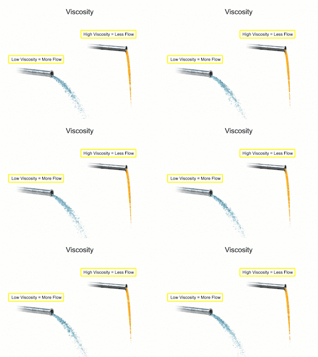
Fluids used in mechanical systems come in many different types. The type of fluid chosen for a particular application depends on its characteristics. One of the most important characteristics of a fluid is its viscosity. Viscosity is defined as a fluids resistance to flow. Fluids with low viscosity flow very easily. Water is a type of fluid with low viscosity. Fluids with high viscosity are more resistant to flow. Honey is a type of fluid with a high viscosity, therefore honey is more viscous than water.


Viscosity index
The viscosity index refers to
changes in viscosity relating
to changes in temperature.
Another characteristic of fluids is the viscosity index. This rating relates the flow of a fluid with its temperature. Many fluids begin to flow more easily as temperature increases. The viscosity index is the measurement of this characteristic. A high viscosity index indicates a small viscosity change with temperature. A low viscosity index indicates a large viscosity change with temperature.

Compressibility is another characteristic of fluids. It measures the change in volume of a fluid as a response to a change in pressure. Fluids such as gases are highly compressible. Their volumes change significantly when placed under pressure. Liquid fluids also have a compressibility factor. Water and petroleum based hydraulic fluid are almost completely incompressible. They don't compress when put under pressure. This characteristic is what allows them to be used to transmit power in fluid systems.
Gas compressibility
Gases are highly
compressible.

Years ago, water was used as the first hydraulic fluid because there was no other liquid available in such large quantities at such a low cost. There are some major draw backs to using water as a working fluid. Due to its low viscosity, it is difficult to pump. Additionally, the speed at which it flows through the system causes an effect known as wire drawing. Wire drawing occurs when the water flow erodes, or scores, a pathway in the metal of machinery as it goes around corners and through orifices. It also has corrosive effects on metal machinery.

Over time petroleum based hydraulic fluids have become much more cost-effective. For starters, it has a lower specific gravity than any other liquid and can be pumped with less power loss. It also lubricates as it works through the system and has little corrosive effects on metal machinery. Flammability is an issue, but with the development of synthetic oils, alternatives to water remain the preferred working fluid.
Liquid compressibility
Water and hydraulic
fluid are almost
completely incompressible.

Several factors should be considered when designing a fluid system that uses a petroleum-based hydraulic fluid. The first is cleanliness. Oil never wears out but it can become so contaminated that it is unfit for further use. Fluid systems frequently employ filters throughout the system to help reduce contaminants. They may also require complete fluid replacement after certain time intervals and this can become cost prohibitive with larger systems. Another factor common to hydraulic fluids are the use of additives. Additives can be used to reduce aeration and the production of bubbles as the fluid travels rapidly throughout the system. They can be used to administer corrosion inhibitors within the reservoir and they can be used as a multi-agent which helps the fluid resist mixing with water.

The choice of modern fluids is so wide that when designing a new system fluid characteristics such as viscosity, viscosity index, cleanliness, filtration and additives should be considered as early as possible in the design process.

Always consult with a fluid systems expert before selecting materials and equipment in any hydraulic system. Their experience and knowledge will help you design an efficient, safe, and cost-effective solution.

For more information, visit https://fluidsystems.processcontrolsolutions.com or call (800) 462-5769.


Information courtesy of www.eicc.edu and funded through a Department of Labor grant under creativecommons.org/licenses/by/4.0/.

Transmitters Used in Industrial Process Control

Pressure transmitter
Pressure transmitter (ifm)
Transmitter is a term used to describe a family of process control field devices. They receive input from a connected process sensor, then convert the sensor signal to an output signal using a transmission protocol. The output signal is passed to a monitoring, control, or decision device for use in documenting, regulating, or monitoring a process or operation.

In general, transmitters accomplish three steps, including converting the initial signal twice. The first step is the initial conversion which alters the input signal to make it linear. After an amplification of the converted signal, the second conversion changes the signal into either a standard electrical or pneumatic output signal that can be utilized by receiving instruments and devices. The third and final step is the actual output of the electrical or pneumatic signal to utilization equipment - controllers, PLC, recorder, etc.

Transmitters are available for almost every measured parameter in process control, and are often referred to according to the process condition which they measure.
Level transmitter
Level transmitters (ifm)


Some examples.

  • Pressure transmitters
  • Temperature transmitters
  • Flow transmitters
  • Level transmitters
  • Vibration transmitters
  • Current, voltage & power transmitters
  • PH, conductivity, dissolved gas transmitters, etc.
Output signals from transmitters, when electrical, often are either voltage (1-5 or 2-10 volts DC) or current (4-20 mA). Power requirements can vary among products, but are often 110/220 VAC or 24 VDC.  Low power consumption by electrical transmitters can permit some units to be "loop powered", operating from the voltage applied to the output current loop. These devices are also called "two-wire transmitters" because only two conductors are connected to the unit. Unlike the two wire system which only needs two wires to power the transmitter and carry the analog signal output, the four-wire system requires four separate conductors, with one pair serving as the power supply to the unit and a separate pair providing the output signal path. Pneumatic transmitters, while still in use, are continuously being supplanted by electrical units that provide adequate levels of safety and functionality in environments previously only served by pneumatic units.
Pressure transmitter
(Winters)

Many transmitters are provided with higher order functions in addition to merely converting an input signal to an output signal. On board displays, keypads, Bluetooth connectivity, and a host of industry standard communication protocols can also be had as an integral part of many process transmitters. Other functions that provide alarm or safety action are more frequently part of the transmitter package, as well.

Wireless transmitters are also available, with some operating from battery power and negating the need for any wired connection at all. Process transmitters have evolved from simple signal conversion devices to higher functioning, efficient, easy to apply and maintain instruments utilized for providing input to process control systems.

To lean more about transmitters, visit https://flowcontrol.processcontrolsolutions.com/ or call Process Control Solutions at 800-528-8997.

EIM TEC2 Electric Actuator with Model 500 Quick-Start Guide

EIM TEC2 Electric Actuator
This Emerson/EIM electric valve actuator is the next generation of the non-intrusive TEC2000 actuator. Robust and compact design that are widely used on valves for marine, oil and gas, chemical, power, and water and wastewater applications.

Features:
  • Superior corrosion protection polyester powder-coating, inside and out, for all environments, 316 stainless steel cover screws, marine-grade, low copper content, aluminum provides compartment and covers with extra corrosion protection.
  • Separately Sealed Terminal Chamber (STC), dual sealed, allows installation wiring to be performed without exposing electronic control components.
  • Anti-condensation space heater thermostat prevents internal condensation due to temperature cycling with solid-state thermo-statically controlled to turn heater off.
  • Large LCD message screen uses icons and text to display status of valve and provide diagnostic data, easy to guide operator through multi-language capable, calibration, setup, and diagnostics.
  • Non-penetrating control knobs operate with vibration resistant Hall-effect switches enabling actuator calibration and diagnostics without opening covers.
  • Double-reduction motor gears provide flexibility, enables worm gearing to operate at lower speeds for minimum wear and long life.
  • Self-locking gearing even during declutching and manual override and valve stem cannot be back-driven under high process pressures or heavy weight of gate.
TEC2 Electric Actuator with Model 500 Quick-Start Guide: